|


...World Wide Distributor of Beryllium-Free Copper Alloys...
Manufacturer of Standard & Custom Components
![]()
Site Updated Often! To ensure proper viewing please Refresh page &
MAKE SURE YOUR BROWSER IS SET TO UPDATE AT EACH VISIT
![]()
Injection Mold Design
Guidelines By Dr. Paul Engelmann and Bob Dealey |
||||||
| Copper Alloys for Conveying Plastic
In Injection Molds The high thermal conductivity of copper alloys makes them ideal materials for the injection mold sprue bushing and runner bars. Three alloys typically are utilized for the mold components, which will have contact with plastic. The copper alloys are:
These Copper alloys have six to nine times greater heat transfer rates than conventional mold steels as indicated by the thermal conductivity. |
||||||
|
||||||
| Sprue Bushing Radius In North America two injection mold nozzle and sprue bushing radii are used, 1/2 and 3/4 inch. To insure proper fit up, the nozzle radius is nominal -.015 Inch, while the sprue radius is nominal +. 015 inch, required tolerances to use. The sprue or runner system must never control the cooling phase and/or overall molding cycle. Plastic in contact with copper alloys will set the sprue and runner faster, allowing more efficient ejection or removal by sprue pickers or robots. |
||||||
|
||||||
| Sprue Bushing Taper To aid in the removal of the sprue from the bushing, a taper of one-half inch per foot is normally used in injection molding. Calculate the sprue orifice at the parting line face, multiply the tangent of the taper angle times the length, plus the "02". Knowing this dimension, informed decisions can be made on primary runner sizing. The sprue frequently controls the molding cycle when larger orifice conventional steel sprue bushings are used. The application of a copper alloy sprue bushing cools the sprue more quickly and efficiently, allowing the molding cycle to be controlled by the piece part. Pressure loss is high in the sprue. This is the only place in the feed system where tile channel progresses from a smaller area to larger. Frequently, smaller orifices are used on long sprue bushings in an effort to reduce the mass. This results in extremely high injection pressure losses, making the part hard to fill. Using a copper alloy sprue bushing allows for an increased size orifice, thus reducing pressure loss while maintaining reasonable cooling times. |
||||||
| Sprue Retention and Anti-Rotation Pressure acting on the parting line face of the sprue, due to projected area of the runner system or part detail, exerts pressure on the sprue bushing. Also, a sprue bushing that is not keyed will rotate creating misalignment with the runner machined into the face of the sprue bushing and the runner system. To prevent these problems, retain and key the sprue into position with the use of a cap screw. Sprue Fit Heat must be transferred from the sprue through the copper alloy sprue bushing to the mold plates. Interference fit is recommended for optimum cooling. The bore through the "A" plate should be nominal size to plus .0005 inches with a surface finish of at least 16 RMS. The shank of the sprue bushing should be the nominal size, plus .0005 to plus .001 inches. |
||||||
| Standard Sprue Bushing Availability Copper alloy sprue bushings with patented stainless steel nozzle seats are commercially available. An insulator between the nozzle and sprue is beneficial in controlling the flow of heat from the nozzle to the sprue. Special sprue bushings may be constructed to suit using standard 1/2 inch per foot sprue bushing tapered drills and reams. Sprue bushings with tapers of up to 3/4 inch per foot have been used for difficult to remove plastics. Care must be taken to insure that the taper is draw polished and free from undercuts or rough surfaces that could hinder sprue removal. |
||||||
|
||||||
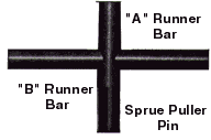
| Injection Mold Runner Bars Runner systems for high cavitation molds normally have larger diameters due to runner balancing. The runner system extends the molding cycles as heat is slowly transferred from the thick plastic to steel mold plates. Inserting copper alloy runner bars in the mold "A" and "B" plates, cooling the runner faster, is beneficial, in reducing the overall molding cycle. |
||||||
| Runner Sizing Runner sizing is dependent on many things, including: plastic material: part size, weight and wall thickness; molding machine capabilities and processing parameters and, the number and placement of the cavities. Each mold is unique and the designer must consider all parameters and options available on an individual case by case basis. Several mold design software packages are available, including Mold Flow and C-Mold, which address sizing of the runner system. One method of runner sizing and balancing used by mold designers starts at the sprue and then works toward the gate. Other designers start with the part wall thickness and work back to the sprue outlet orifice. The normally recommended procedure is that, in the direction of plastic flow, the runner area always goes from larger to smaller. Never from a smaller area to a larger area. |
||||||
|
||||||
|
||||||
| Runner Bar Mating Best results are obtained by designing and building the runner bars to have zero to negative contact with each other when the mold is closed. This will prevent any deformation on the parting line surfaces that could result from high clamping pressures exceeding the compressive strength of the alloy. To accomplish this, the "A" and "B" runner bars should be flush to minus .001 inch on each side of the mold. This allows the mold base and/ or cavity and core inserts to receive machine clamp force, not the runner bars. Care must be taken to understand the characteristics of the plastic being molded and clearance should be short of allowing the runner system to flash. Additionally, it is important to insure that the mating halves of the runner system are in perfect alignment, with no mismatch at the parting line, to maximize plastic flow efficiency |
||||||
| Runner Bar Cooling The runner system must never control the molding cycle. To insure proper temperature control of the runner bars, cooling channels should be placed directly into the both the "A" and "B" side inserts. The cross-drilled holes should be blocked with a plug containing an "0" ring and a straight thread plug. Due to the high thermal conductivity of the copper alloys and the tendency to thermal cycle rapidly, tapered thread systems must be avoided in the copper alloys to prevent cracking. With the increased cooling rate of the copper alloys and proper cooling arrangements, larger diameter runners can be used in a mold equipped with copper alloy runner bars. Almost without exception, runner diameters one or two sizes larger can be set up quicker with the copper alloys, over traditional mold steels. |
||||||
| Sprue Puller A reverse taper sprue puller, 30 for stiffer materials and 50 for flexible materials, is recommended to insure sprue removal. To rapidly cool the undercut machine, the puller directly into the runner bars or a copper alloy insert. |
||||||
| Acknowledgments The injection mold design guidelines were written by Dr. Paul Engelmann, Associate Professor Western Michigan University and Bob Dealey, Dealey's Mold Engineering, with the support of Dr. Dale Peters, for the Mold Marketing Task Group of the Copper Development Association. Kurt Hayden, graduate research assistant. WMU generated the illustrations. Research conducted by WMU students in the plastics program. |
||||||
Disclaimer |
||||||
|
|
||||||
|
||||||
|
Copyright © 2024 by Performance Alloys &
Services, Inc |